|


| |
Drilling with the Xs drill
casing systems
Preparing the equipment
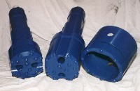
• Place the casing
crown over the end of the casing taking care to align the crown to the square
edge of the casing. Tack weld in three places to hold the crown in position then
weld around the upper edge of the crown using an electrode approx 3/32”
diameter. Grind the weld after welding to minimise interference between crown
and the drilled hole. In cold weather it is recommended that the components to
be welded should be preheated.
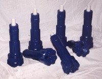
Insert the Driver/Bit into the DTH Hammer in the conventional manner, and if a
short starter tube is to be used, attach it to the DTH hammer at this time.
Starter Casing
• The crown and first casing assembly
should be cut to match the length of the DTH Hammer (or DTH Hammer and starter
tube) minus 8” this should put the top of the casing to approximately 2”- 3”
below the top wrench flats. This will allow access to the wrench flats and
enable the adding and removal of drill tubes as drilling progresses.
Casing length
• Ideally subsequent casing should
match the length of each drill pipe. However many casings are of random length,
and care should be taken when adding random casings, not to cover the top wrench
flat of the drill pipe, or be too low for the reach of the diverter. It is
desirable to measure each casing and record the length on it so that it is known
before adding to the column. Occasionally a casing can be cut to offset these
discrepancies.
Assembling the Driver and Crown
• Locate the Diverter into the raised
position by raising the control handle.
With the winch raise the driver/bit, DTH hammer and starter tube assembly and
attach it to the thread of the saver sub on the rotation head. Raise the
assembly and rotation head high into the drill mast to allow the casing to be
positioned. With the winch, lift the starter casing with the crown onto the
drill table, and secure. Slowly guide the driver bit into the starter casing and
feed it all the way to the crown. By lifting the driver up and down and turning
the driver a few degrees each time, locate the driver through the crown. The
driver is in position when the driver protrudes through the crown approximately
2”. Turn the driver slowly in the normal drilling direction and the crown will
lock onto the driver. Lower the diverter by operating the up/down lever until
the diverter locates on top of the casing.
Starting to Drill
• Drilling is started by lowering the
starter casing with the driver to the ground whilst slowly rotating with the
hammer air supply partially on. As the driver bit closes into the DTH hammer, it
will start to drill.
(Note, it is easier to start a casing hole with an air pressure of less than
200psi) It is imperative that the operator monitors the discharge pipe to verify
a good flow of debris, once the casing is penetrating the ground, it is
advisable to commence water or foam injection. When the casing is level with the
drill table, drilling is stopped and the hammer air turned off. The diverter is
raised (if using Xs air diverter) to expose the flat on the top of the starter
tube, which can then be secured in the table with the drill tube wrench. The
rotation head can then be unscrewed and travelled to the top of the mast.
Adding Casing
• The length of casing should match
the length of the drill pipe. Many casings are of random length, and care should
be taken when adding casings not to cover the top wrench flat of the drill pipe.
It is advantageous to measure each casing and record the length so that
occasionally a casing can be cut to offset these discrepancies.
Drill tubes need to be inserted into the casings whilst in the horizontal
position, preferably on the ground; this can be done manually or with a draw
cable. To lift the assembly into the drill mast, it is recommended that a proper
double hook and chain be attached to the winch. The drill tube/casing assembly
is then raised into the mast, the upper drill tube thread aligned into the saver
sub and the two screwed together.
The winch with the casing still engaged then can be lowered until the hook sits
on the drill table leaving the drill tube hanging from the rotation head.
The winch rope can now be slackened allowing the top loop to run down the
casing.
A sling can now be attached to the casing then the casing lifted enough to allow
the hook to be disengaged. At this point the drill tube is to be engaged and
tightened on to the tube held by the wrench below. The casing is then lowered
onto the previously drilled casing, clamped into position and tack weld in three
places. The casing joint should then be welded all around using an electrode
approx 3/32” diameter. In cold weather it is recommended that the components to
be welded should be preheated.
The sling can now be removed from the casing.
Continuing to Drill
• Locate the Diverter into the lower
position by raising the control handle, if using Xs air diverter) and ensure the
diverter is located on the top of the casing.
Drilling can now recommence by slowly rotating with the hammer air supply on,
and water or foam injection engaged As the driver bit closes into the DTH hammer
it will start to drill. With the addition of each casing only enough down thrust
should be applied to make the DTH hammer run smoothly. Again it is important
that the operator monitors the discharge pipe to verify a good flow of debris.
Drilling can continue in this manner until the top of casing is level with the
drill table, when the whole process starts over again.
Retrieving the driver bit
• When the casing is drilled to the
desired depth, the driver/bit can be disengaged from the casing crown by reverse
rotation. It helps the disengagement process if the driver bit is thoroughly
flushed with air water, and foam if available. This can be done with the DTH
hammer in the lifted position to allow the hammer to go into the by-pass mode
which allows more flushing air and fluids to pass. The driver should then be
rotated in reverse approximately 1/8 of a turn and then lifted. If the driver is
disengaged, the drill tubes will rise leaving the casing in the hole. If the
driver bit does not disengage on the first attempt, rotate it back and for into
and out of the locked position with the rotation motor. After the driver/bit is
disengaged pull all the drill tubes out of the casing in the conventional
manner, with the hammer air on and slowly rotating in the drilling direction.
Drilling below the Casing
• Drilling below the casing with the
same diameter as the casing, the specially designed GeoRocFor’s “Square Bit TM”
is required. This drill bit has two opposing flats, which allow it to pass
through the flats on the casing crown. The driver should be exchange for the
square bit then the hammer bit and drill tubes lowered into the drill hole in
the conventional manner. The operator should be aware of the casing depth so
that when the square bit is approaching the casing crown, the hammer air supply
can be turned off. The square bit should be rotated slowly in the drilling
direction as it approaches the crown, this will help the flats line up on the
bit and crown. When the flats are aligned the drill tubes will drop
approximately 6”, after which drilling can commence.
Relocating the Driver Bit
• Should it be found necessary to
advance the casing further after the driver bit is disengaged, it can be
re-engaged by lowering into the casing whilst inducing the flushing fluids and
rotating the driver/bit slowly in the direction of drilling. When the driver
contacts the crown, continue to turn slowly with the hammer air off, until the
drill tube is seen to drop. The operator can ascertain if the driver/bit is
engaged in the crown by lifting the drill string, if the drill string lifts
without the casing then the driver/bit is not engaged. If resistance to lifting
is felt then the driver and crown are engaged.
© Georocfor, 2006
|