![]()


|
Xs F drill |
|
|
|
|
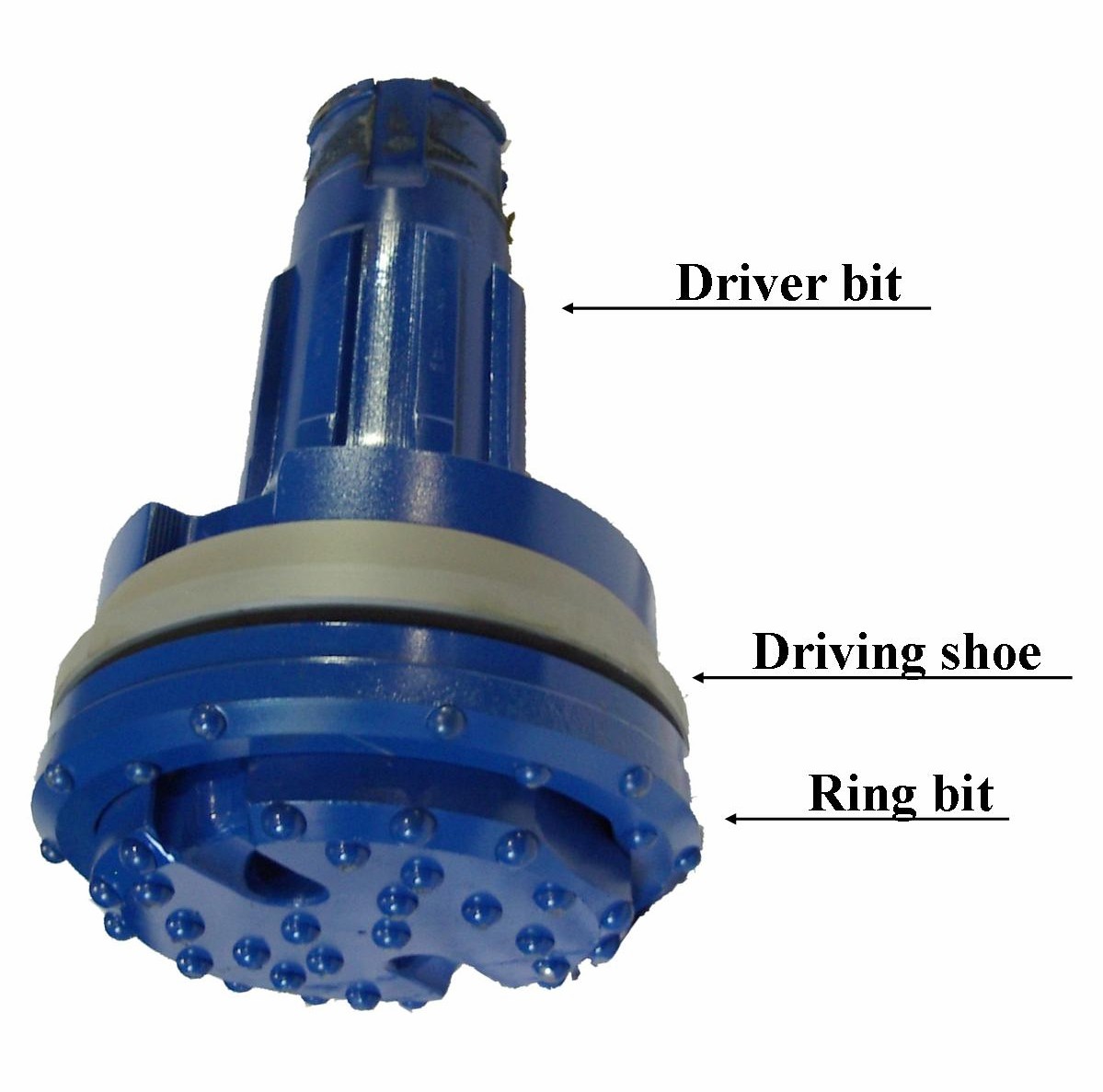
•Description: The Xs F (Floating) system is especially designed for piling, micro piling, anchor installation and other civil engineering applications, in shallow holes, whether the casing is left in the hole or pulled. The Xs F can be used with any size of casing. The life of this system is much improved because of its geometry which has two (2) internal shoulders (donut). One transfers impact to the drive shoe, giving the necessary force to drive down casing. The second transfers energy directly to the crown bit for drilling. •Advantages: Advantages over Eccentric systems Advantages over other Ring bit systems Advantages over wing bit systems •:Components:
Driver bit: The driver bit is the device that transfers impact and rotation to the crown bit for drilling. The driver bit locks into two flats on the casing crown and they act together as a standard drill bit, both the driver bit and the crown have tungsten carbide buttons. The Driver bit drills a pilot hole of 3" below the crown to guide the direction of the casing in rough drilling. Afterwards this pilot space below the crown allows the square bit to turn without touching the crown. Ring bit: The crown bit is a single unit with Tungsten carbide, held on the driver only by the locking surface. Driving shoe: The driving shoe is welded to the casing, and received the impact from the driver bit to drive down the casing. The drive shoe is the same OD as the casing to allow easy retrieval. Square bit: The drill through bit is specially shaped to pass through the crown's flats, and to drill the sub-casing hole to a maximum hole diameter, enabling in most of the cases, the use of a larger diameter hammer than the competition. •Impact zone: Direct energy from the hammer is transferred to the Ring bit through two (2) recesses formed by the locking surface plus a projection all around the periphery of the driver (donut). •Evacuation: Two (2) big air holes are drilled in the face of the bit (drilling end). Those holes are directly connected to two (2) large flushing air ways, placed at 160 degree between each other; these flushing grooves transfer the drill debris from the drilling end of the driver up to the hammer zone. To help keeping a good flow of debris, two (2) other smaller air holes in the flushing air ways, help give the cuttings some velocity. |
|
Send mail to
luc@georocfor.ca with
questions or comments about this web site.
|